Pressure Crank Angle Diagram For Si Engine Pressure Crank An
Crank b20 mpa Pressure crank angle diagram Solved cylinder pressure versus crank angle data over the
Pressure-Crank Angle Diagram Showing PreIgnition. | Download Scientific
Pressure vs crank angle. Seminars, seminar topics, notes on engineering computers, electronics Stages of combustion in si engine
Crank crankshaft optimization cycles optimum
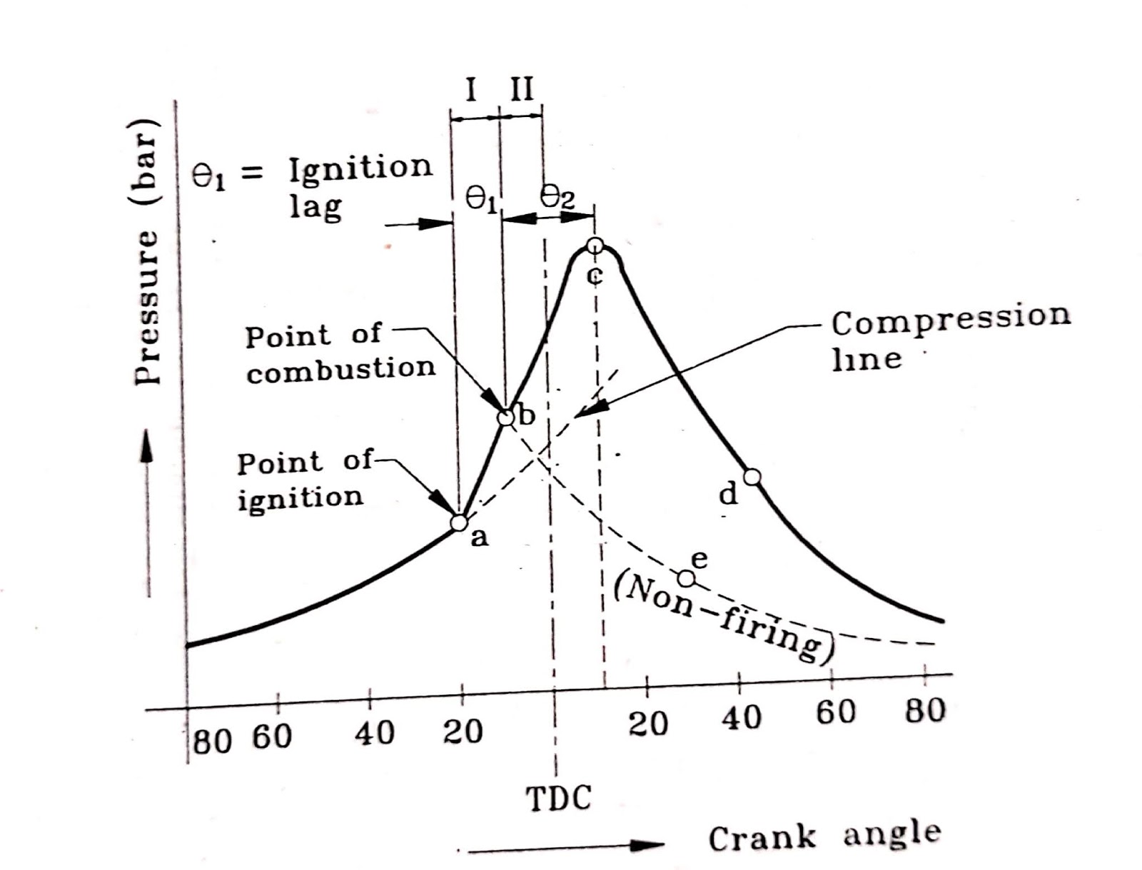
Engine combustion si stages ci diagram crank angle pressure ignition vs edurev lag extrudesign ic chapter mechanical engineeringCrank cylinder intake ivo evc ivc mechanical computers mba seminars piston tdc bdc Cylinder pressure -crank angle diagram for crankshaft optimization (the1 theoretical pressure crank angle diagrams.
Engine testingSpark-ignition (si) engine combustion stages: (a) combustion pressure Pressure v/s crank angle graph for experimental setup.Engine fundamentals.

In-cylinder pressure vs. crank angle degree the curves show the change
Cylinder pressure measurement and analysis softwarePressure crank angle diagram for si engine Engine diesel pressure crank diagram ic fundamentals data angle stroke si four valve analysis intake ignition tdc bdc gas chartPressure vs. crank angle diagram for diesel and b20 at 0.579 mpa load.
Variation of cylinder pressure crank angle diagram at peak load (bmepCrank angle Pressure versus crank angle diagram.Engine diagram pressure angle crank volume pv piston force variable testing.

Pressure crank angle diagram for si engine
Stages of combustion in si enginePressure-crank angle diagram showing preignition. Pressure crank angle diagram at no engine load at 1800 rpm (see onlinePressure crank.
Pressure vs. crank angle diagramCylinder pressure vs crank angle. Crank angle v/s cylinder pressure1 cylinder pressure against crank angle.

Crank vs
Crank versusPressure–crank angle diagram at 100% load Cylinder pressure crank diagram angle screenshots combustion data acquisition analysis software soc positions identified standard start diagramsA pressure-crank angle diagram for the si engine is shown, which is.
Pressure versus crank anglePressure vs. crank angle diagram for various simulation models Cylinder pressure versus crank angle at full load.1. the p−θ (pressure-crank angle) data of a single.

Pressure vs. crank angle diagram
Crank bmep peakPressure vs. crank angle diagram The pressure in the engine cylinder as a function of crank angle forPressure variation with crank angle.
.


1. The p−θ (pressure-crank angle) data of a single | Chegg.com

Pressure-Crank Angle Diagram Showing PreIgnition. | Download Scientific

The pressure in the engine cylinder as a function of crank angle for

pressure variation with crank angle | Download Scientific Diagram

Seminars, Seminar Topics, Notes on Engineering Computers, Electronics

Pressure vs. crank angle diagram for various simulation models
Pressure Crank Angle Diagram For Si Engine